|
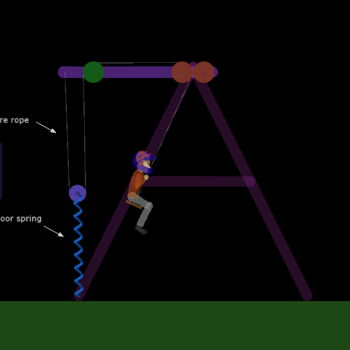
Title: Zero Length Spring Swing II
Rating: 5.625
Filesize: 72.56 kB
Downloads: 1240
Comments: 5
Ratings: 2
Date added: 2015/11/17 23:13:13
Made with: Algodoo v2.1.0
Rating: 
|
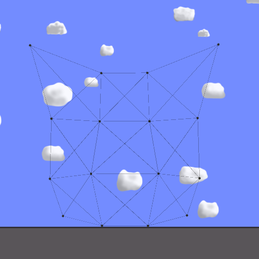
Title: Cat or dog polygones made of springs
Rating: 5
Filesize: 34.67 kB
Downloads: 425
Comments: 1
Ratings: 1
Date added: 2010/06/22 13:30:56
Made with: Algodoo before v1.8.5
Rating: 
|
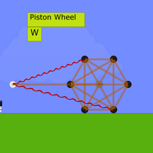
Title: PolyBuild Physics Game (1.2)
Rating: 6.1111
Filesize: 81.33 kB
Downloads: 1794
Comments: 2
Ratings: 3
Date added: 2022/01/07 02:41:14
Made with: Algodoo v2.1.0
Rating:
|
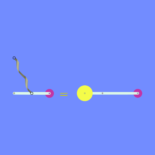
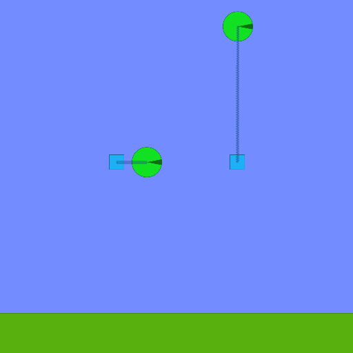
Title: Zero-Length Spring
Rating: 5.625
Filesize: 13.67 kB
Downloads: 583
Comments: 4
Ratings: 2
Date added: 2014/06/14 23:19:18
Made with: Algodoo v2.1.0
Rating:
|
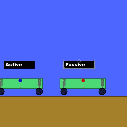
Title: Active Suspension and Web Generator
Rating: 5
Filesize: 17.74 kB
Downloads: 921
Comments: 0
Ratings: 1
Date added: 2013/01/14 07:30:53
Made with: Phun
Rating:
|
Title: Scripted rope and uhhhhhh reverse rope
Rating: 5.625
Filesize: 9.94 kB
Downloads: 696
Comments: 2
Ratings: 2
Date added: 2023/10/12 21:18:44
Made with: Algodoo v2.1.0
Rating:
|