Image:
 Author: Xray Group: Default Filesize: 2.16 MB Date added: 2019-10-15 Rating: 7.1 Downloads: 3865 Views: 852 Comments: 9 Ratings: 6 Times favored: 0 Made with: Algodoo v2.1.0 Tags:
|
Q: What is this?
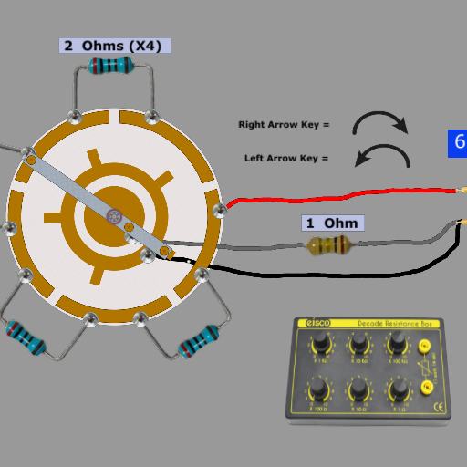
A: It is one resistor selector switch including its associated resistors which are part of an electronic testing device known as a resistor substitution box.
Q: What's a resistor substitution box, and what is it used for?
A: When an electrical engineer or technician is designing or repairing an electronic device, it is sometimes very handy and convenient to try different resistor values in order to determine how the electronic device will behave with different resistor values. The resistor substitution box is basically a large number of individual resistors that can be selected simply by turning knobs on the box. When the electronic device under test is behaving as desired, the engineer can read the resistance values that the knobs are pointing to, and can then install that value resistor by soldering it into the electronic circuit.
Q: What's so special about this particular type of selector switch, and why is it different from most other standard selector switches?
A: In nearly all low-cost or standard "hobbyist" resistor substitution boxes, they use what are called "single pole, 10 position rotary switches" which add or subtract a single resistor of equal value with each switch detent (position). The diagram in the lower-right portion of the scene shows how a standard or traditional rotary switch in a resistor substitution box is wired. Notice that there are nine resistors and ten positions, which provides resistance values of zero to nine, or zero to 90, or zero to 900, etc.
The rotary switch in this scene is special because of the way that it functions, and it also requires a total of 5 resistors to produce the same 10 resistor values (including zero) as noted above. It does this by alternately switching the "units" value resistor in and out of the circuit. In other words, at every even position of the switch (0, 2, 4, 6, etc), the units resistor is short-circuited via certain contacts on one of the copper tracks. At every odd position (1, 3, 5, 7, etc) the units resistor is allowed to be in series with one or more of the other resistors.
Q: Wouldn't such an unusual or "custom made" switch be much more costly than adding a few more resistors and using a standard single-pole switch?
A: Yes and No! For a low-cost or hobbyist type of box, such a switch would be way too expensive to use, considering the fact that high tolerance resistors (greater than 1%) are very cheap. But when a high precision, high current substitution box is required, then the cost of low tolerance (typically 0.1% or less) and high current (many amps in some cases) resistors has a considerable impact on the total cost of the box, and therefore saving money by using fewer resistors and using special switches makes sense.
Q: Why did I make an Algodoo scene of a resistor substitution box switch and its associated circuitry?
A: Because I thought that this switching arrangement was a very clever mechanical and electrical design which I wanted to share with others who might appreciate it.
Feel free to leave questions in the comments section if you don't quite understand how this works, and would like some additional explanation. In case you haven't figured it out, the fast moving white tracer shows the circuit paths that the electrons would take at different switch positions. This is just one switch with associated resistors in a substitution box which typically has anywhere between 3 or 4 to as many as 10 or more switches. Also, you are looking at the REAR portion of the switch which is hidden inside of the box. The switch is turned through a shaft and a knob which extends outside of the box. Included in the scene is an image of a typical decade resistor substitution box.
Update: Added picture of a resistor substitution box. |


.png)